TR
TR EN
EN

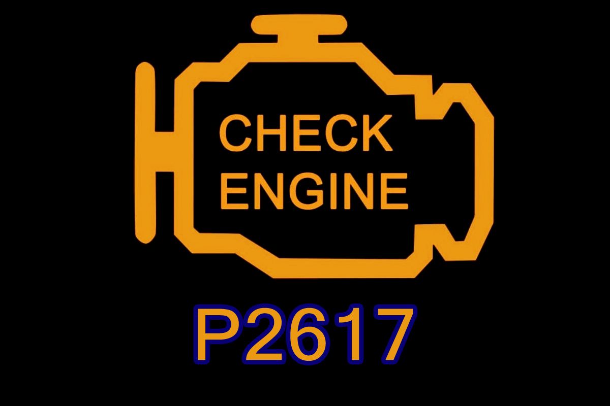
P2617 Crankshaft Position Signal Output Circuit/Open
P2617 is an OBD-II diagnostic trouble code indicating that the engine control system has detected a problem with the crankshaft position signal output circuit.
The wording is important here. This code does not simply mean that the crankshaft position sensor has failed.
The “Output Circuit/Open” portion indicates that the control module has detected an interruption, abnormal electrical condition, or missing expected signal in a circuit responsible for carrying or providing the crankshaft position signal.
Because crankshaft position information is fundamental to engine operation, P2617 can range from a code with relatively minor symptoms to a fault that causes hard starting, stalling, or a complete no-start condition.
Why the Crankshaft Position Signal Matters
The crankshaft position signal tells the engine control module where the crankshaft is and how fast it is rotating.
The ECM uses this information for critical engine-control functions such as:
-
Fuel injection timing
-
Ignition timing on gasoline engines
-
Injector synchronization on diesel engines
-
Crankshaft speed calculation
-
Misfire detection
-
Camshaft/crankshaft synchronization
-
Variable valve timing control
-
Engine starting strategy
During cranking, the control module needs to know that the crankshaft is rotating and where it is positioned.
If the expected signal disappears, becomes interrupted, or cannot be transmitted correctly, the ECM may no longer be able to synchronize fuel and ignition events accurately.
What Does “Output Circuit/Open” Mean?
This is where P2617 differs from a simple crankshaft position sensor circuit code.
“Output” refers to a signal being generated or transmitted from one part of the system to another.
“Circuit” refers to the electrical path carrying that signal.
“Open” indicates an interruption or loss of the expected electrical path or signal.
The fault can therefore involve:
-
Broken wiring
-
A disconnected connector
-
A damaged terminal
-
Poor terminal contact
-
Corrosion
-
An internal sensor or signal-generator problem
-
A problem inside the control circuit
-
An interruption between control modules on systems where the signal is electronically transmitted
It is not correct to interpret “open” as meaning that the crankshaft itself has a mechanical problem.
The Crankshaft Position Sensor May Not Be the Problem
A crankshaft position sensor is an obvious suspect, but replacing it immediately is not always the correct repair.
For example, a perfectly functional sensor can generate a proper signal, but that signal may be lost because of a damaged wire.
Similarly, a connector terminal that has lost tension may work normally when the engine is cold but lose contact because of vibration or thermal expansion.
A damaged reluctor or trigger wheel can also produce an abnormal crankshaft signal even though the sensor itself is electrically healthy.
This is why P2617 should be diagnosed as a signal-path problem, rather than automatically as a sensor failure.
Common Causes of P2617
Damaged crankshaft position signal wiring
A broken or partially broken wire can interrupt the signal.
Wiring damage may occur because of:
-
Engine vibration
-
Heat
-
Contact with moving components
-
Previous repairs
-
Rodent damage
-
Oil contamination
-
Harness chafing
A wire can sometimes appear intact externally while being broken internally.
Loose or damaged connector
The crankshaft position sensor connector should be inspected carefully.
Possible problems include:
-
Bent pins
-
Corroded terminals
-
Loose terminals
-
Poor terminal tension
-
Water intrusion
-
Oil contamination
-
Damaged locking mechanism
Faulty crankshaft position sensor
The sensor itself can fail electrically or internally.
Some sensors fail completely, while others become unreliable only under certain conditions such as high temperature, vibration, or particular engine speeds.
Damaged reluctor or trigger wheel
The crankshaft position sensor reads a pattern generated by a reluctor, trigger wheel, tone wheel, or similar component.
If that component is damaged, displaced, cracked, contaminated, or mechanically altered, the sensor may not produce the expected signal.
Incorrect sensor installation
An incorrect air gap, incorrectly positioned sensor, wrong sensor type, or damaged mounting location can interfere with signal generation.
This is particularly worth checking after recent engine, transmission, clutch, timing, or sensor work.
Poor power or ground
Depending on the sensor design, a reliable power supply and ground may be required.
A problem in either circuit can prevent the sensor from producing the expected signal.
Electrical interference
Poorly routed wiring, damaged shielding, or interference from other electrical components can distort sensitive position signals.
This can be particularly relevant to variable-reluctance or other high-speed timing signal systems.
Timing or mechanical problem
A mechanical problem can sometimes make an electrical signal appear abnormal.
Potential causes include:
-
Damaged timing components
-
Excessive timing-chain stretch
-
Incorrect camshaft timing
-
Damaged crankshaft trigger wheel
-
Excessive crankshaft movement
-
Mechanical damage affecting sensor-to-trigger alignment
ECM or signal-processing fault
The engine control module is possible, but it should normally be considered only after the sensor, wiring, connectors, power supply, grounds, trigger mechanism, and signal integrity have been properly tested.
Symptoms You May Notice
P2617 can produce very different symptoms depending on whether the signal is completely lost or only occasionally interrupted.
Possible symptoms include:
-
Check Engine Light
-
Extended cranking
-
Hard starting
-
Engine stalling
-
Intermittent no-start
-
Complete no-start
-
Rough running
-
Hesitation
-
Loss of power
-
Engine misfires
-
Tachometer behaving abnormally
-
Reduced engine performance
-
Limp-home operation
If the crankshaft signal disappears completely while the engine is running, the engine may stall because the ECM can no longer accurately determine crankshaft position.
Why the Engine May Still Start With P2617
An intermittent or marginal signal fault does not necessarily prevent the engine from starting.
The sensor may produce a usable signal most of the time, with occasional interruptions.
For example, the engine may:
-
Start normally in the morning
-
Stall after warming up
-
Restart after cooling down
-
Run normally at idle
-
Lose the signal during acceleration
-
Experience occasional extended cranking
This type of behavior can make the fault particularly difficult to reproduce.
A loose connector or internally damaged wire can produce exactly this kind of intermittent behavior.
How P2617 Is Diagnosed
The diagnosis should concentrate on the entire crankshaft signal path.
1. Scan for all codes
Start by scanning all available control modules.
Pay attention to codes involving:
-
Crankshaft position
-
Camshaft position
-
Engine speed
-
Synchronization
-
Misfires
-
Ignition
-
Fuel injection
-
Communication
Related codes can help determine whether P2617 is the primary fault or part of a larger synchronization problem.
2. Check freeze-frame information
If freeze-frame data is available, determine when the code occurred.
Useful information includes:
-
Engine RPM
-
Vehicle speed
-
Engine temperature
-
Battery voltage
-
Engine load
-
Starting/cranking condition
A fault occurring only during cranking points the diagnosis in a different direction from one occurring during high RPM.
3. Inspect the crankshaft position sensor
Locate the sensor according to the manufacturer's service information.
Inspect:
-
Sensor body
-
Mounting
-
Connector
-
Wiring
-
Sensor tip where applicable
-
Harness routing
Look for signs of oil contamination, physical damage, excessive heat, or contact with moving components.
4. Inspect the wiring carefully
Follow the harness from the sensor toward the engine-control system.
Check for:
-
Broken wires
-
Chafing
-
Melted insulation
-
Corrosion
-
Previous repairs
-
Loose connections
-
Poor terminal contact
A visual inspection should not be considered sufficient by itself.
5. Check power and ground
If the sensor requires an external power supply, verify that the correct supply is present under the manufacturer's test conditions.
Ground integrity should also be checked.
Do not assume that a measured ground or power voltage automatically proves the circuit is healthy. Voltage-drop testing under operating conditions can reveal resistance that a basic voltage check misses.
6. Verify the signal
This is one of the most valuable parts of the diagnosis.
Depending on the sensor design, the crankshaft signal may need to be examined with:
-
A suitable multimeter
-
Scan-tool live data
-
An oscilloscope
-
Manufacturer-specific diagnostic equipment
An oscilloscope can be particularly useful because it allows the technician to see whether the waveform is present, stable, and consistent during cranking and engine operation.
There is no single waveform or voltage value that applies to every vehicle.
Crankshaft Position Sensor Types Matter
Not every crankshaft position sensor operates in the same way.
Common designs include:
Variable-reluctance sensors
These generate an alternating electrical signal as the trigger wheel passes the sensor.
The signal characteristics change with engine speed.
Hall-effect sensors
These typically require a power supply and produce a digital switching signal as the trigger target passes the sensor.
Because the electrical behavior is different, the diagnostic procedure must match the sensor design.
Testing a Hall-effect sensor as if it were a conventional variable-reluctance sensor can produce an incorrect diagnosis.
Check the Crankshaft Trigger Mechanism
If the sensor and wiring appear healthy, the mechanical trigger should be investigated.
The control module is expecting a specific pattern from the crankshaft.
Problems such as:
-
Missing or damaged teeth
-
A damaged reluctor
-
Incorrect trigger-wheel position
-
Excessive runout
-
Foreign material
-
Incorrect sensor gap
can distort the expected signal.
On some engines, the reluctor is integrated into the crankshaft or another internal component, making inspection more involved.
P2617 After Engine or Timing Work
If P2617 appeared after engine repairs, timing work, transmission removal, clutch work, or sensor replacement, the recent work should be considered carefully.
Possible issues include:
-
Sensor not fully seated
-
Damaged connector
-
Harness routed incorrectly
-
Wiring trapped against another component
-
Incorrect sensor
-
Damaged reluctor
-
Incorrect mechanical timing
-
Missing fastener or incorrect sensor mounting
-
Connector left partially engaged
A fault that appears immediately after mechanical work deserves a careful inspection of anything that was disturbed during that repair.
Could a Weak Battery Cause P2617?
Low system voltage can interfere with electronic systems, particularly during engine cranking.
A weak battery, poor battery connection, or poor engine ground can therefore contribute to abnormal sensor operation or module behavior.
However, a weak battery should not automatically be blamed for P2617.
If the battery voltage collapses during cranking, there may be several voltage-related codes stored alongside the crankshaft signal code.
Checking battery condition and cranking voltage is therefore worthwhile, especially when the vehicle has difficulty starting.
P2617 and Camshaft Position Codes
The crankshaft and camshaft signals work together to establish engine synchronization.
If a vehicle has P2617 along with a camshaft position or synchronization code, the diagnosis should not be limited to the crankshaft sensor.
The technician may need to examine:
-
Crankshaft signal
-
Camshaft signal
-
Timing relationship
-
Timing-chain or belt condition
-
Trigger patterns
-
VVT operation
-
Mechanical timing
A problem with one signal can sometimes cause the control module to report additional synchronization-related faults.
No Universal Resistance or Voltage Specification
It is tempting to test a crankshaft position sensor with a generic resistance value found online.
That can be misleading.
Different sensor designs have different electrical characteristics, and some sensors cannot be accurately diagnosed simply by measuring resistance.
The correct procedure should be based on the vehicle manufacturer's specifications and wiring diagram.
The same principle applies to signal voltage, power supply, and waveform.
Can You Drive With P2617?
If P2617 is intermittent but the vehicle currently runs normally, it may continue to operate temporarily.
However, this is not a code that should be ignored.
A crankshaft signal can fail completely without much warning. If that happens, the engine may stall or refuse to restart.
Driving should be avoided if the vehicle is:
-
Stalling
-
Difficult to start
-
Losing power
-
Misfiring
-
Showing multiple engine-control warnings
-
Experiencing intermittent loss of engine RPM information
A sudden engine stall can create a safety problem, particularly in traffic.
What Should Be Replaced?
P2617 does not identify one specific failed component.
Depending on the diagnosis, the repair could involve:
-
Crankshaft position sensor
-
Sensor connector
-
Damaged wiring
-
Electrical terminals
-
Power or ground connection
-
Trigger/reluctor component
-
Timing-related mechanical component
-
ECM or another signal-processing component
The sensor should be replaced only after the evidence points toward the sensor itself.
P2617 vs. Other Crankshaft Position Codes
P2617 specifically refers to the crankshaft position signal output circuit/open.
Other crankshaft-related DTCs may describe:
-
Sensor circuit malfunction
-
Low input
-
High input
-
Intermittent signal
-
Range/performance
-
No signal
-
Incorrect correlation
These descriptions matter because they point toward different electrical or signal conditions.
For example, an open circuit suggests an interruption in the signal path, while a range/performance code can indicate that the signal exists but does not behave as expected.
The Real Diagnostic Question
P2617 is easiest to understand if the problem is viewed as a chain:
Crankshaft movement → trigger/reluctor pattern → position sensor → wiring/connector → signal processing → engine control module
A fault anywhere along that chain can potentially prevent the expected crankshaft position information from reaching the control system.
That is why simply replacing the crankshaft position sensor is not always the answer.
A proper diagnosis should confirm whether the sensor is generating the correct signal, whether that signal is reaching the control system without interruption, and whether the crankshaft's mechanical trigger is producing the expected pattern. Once those three areas are verified, the cause of P2617 can usually be narrowed down considerably.