TR
TR EN
EN

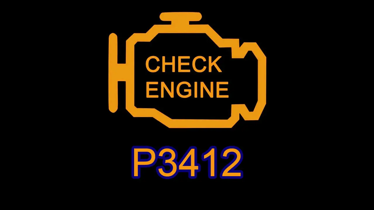
P3412 Cylinder 2 Deactivation/Intake Valve Control Circuit High
The P3412 trouble code indicates that the engine control module (ECM/PCM) has detected a higher-than-expected electrical signal in the cylinder 2 deactivation/intake valve control circuit. This code is related to the electrical control circuit and does not automatically mean that the intake valve itself has mechanically failed.
Depending on the engine design, cylinder deactivation and intake valve control may use an electrically controlled solenoid, actuator, or a combination of electrical and hydraulic components. When the ECM detects an abnormal high signal in the relevant control circuit, it stores P3412 and may disable the affected function.
What Does P3412 Mean?
The key term in P3412 is “Circuit High.”
This means the ECM has detected a voltage or electrical signal that is higher than the expected value for the cylinder 2 deactivation/intake valve control circuit.
Several different electrical problems can produce this condition. For example, a control wire may be shorted to a power supply, a component may have an internal electrical fault, or the circuit may not be behaving as expected because of a wiring or connector problem.
The exact circuit configuration varies between manufacturers and engines, so the vehicle-specific wiring diagram and service specifications should be used during diagnosis.
What Is the Cylinder 2 Deactivation/Intake Valve Control System?
Some engines use cylinder deactivation or specialized valve-control systems to change how the engine operates under certain conditions.
The ECM controls the system according to engine speed, load, temperature, throttle position, and other operating parameters. An electrical command may activate a solenoid or actuator, which then controls the valve mechanism.
Depending on the engine, engine oil pressure may also be involved in physically changing the operation of the valve mechanism.
Because the ECM monitors the electrical circuit, a problem with the wiring or control component can trigger P3412 even when there is no physical damage to the intake valve itself.
Symptoms of P3412
The symptoms can vary depending on the vehicle and the way its valve-control system operates.
Possible symptoms include:
-
Check Engine Light
-
Rough idle
-
Engine vibration
-
Reduced engine performance
-
Poor acceleration
-
Hesitation
-
Engine misfire
-
Increased fuel consumption
-
Reduced fuel economy
-
Irregular engine operation
-
Difficult starting in some cases
-
Cylinder deactivation function becoming unavailable
Some vehicles may continue to drive relatively normally while storing the code. The ECM may simply disable the affected valve-control function to prevent further problems.
Common Causes of P3412
Several electrical faults can cause a high signal in the cylinder 2 control circuit.
Short to power
A control wire may come into contact with a battery-voltage or other power-supply circuit. This can cause the ECM to detect a higher-than-expected voltage.
Damaged wiring
Engine wiring is exposed to heat, vibration, oil, moisture, and physical movement. Damaged insulation or incorrectly routed wiring can create an abnormal electrical signal.
Damaged connector or terminal
A loose, corroded, bent, or incorrectly positioned terminal can alter the electrical characteristics of the circuit.
Faulty control solenoid
If the system uses a solenoid, an internal electrical fault can cause the control circuit to behave incorrectly.
Faulty actuator
An electrically controlled actuator associated with the valve-control system can also be responsible for the abnormal signal.
Incorrect wiring repair
A previous repair may have connected the wrong wires together or accidentally connected the control circuit to a power supply.
Abnormal power supply
An issue in the electrical supply circuit can result in voltage higher than the value expected by the control module.
Poor ground
A problem with the ground circuit can alter the voltage seen by the ECM and affect the operation of the control component.
ECM control circuit fault
In less common cases, the ECM itself may have a problem with the internal driver or monitoring circuit associated with the system.
How Is P3412 Diagnosed?
A proper diagnosis should begin by determining why the ECM sees a high electrical signal rather than immediately replacing the valve or control solenoid.
First, the code should be confirmed with a diagnostic scanner. Freeze-frame data should also be reviewed when available. This information can show the engine speed, temperature, load, and other conditions present when the code was stored.
The technician should then identify the exact cylinder 2 control circuit using the manufacturer's wiring diagram.
Inspect the Wiring and Connectors
The wiring should be visually inspected from the ECM side to the relevant control component.
Look for:
-
Damaged insulation
-
Burned wiring
-
Melted sections
-
Chafing
-
Wires touching power sources
-
Loose connectors
-
Corroded terminals
-
Bent pins
-
Terminals pushed backward into the connector
-
Oil or water contamination
-
Poorly repaired wiring
The inspection should pay particular attention to areas where the harness passes close to hot engine components or moving parts.
Check the Circuit Voltage
The voltage in the affected control circuit should be measured according to the manufacturer's diagnostic procedure.
The measured value should then be compared with the manufacturer's specifications.
There is no single universal voltage value that can be applied to every vehicle with P3412. Different manufacturers use different control strategies, so generic measurements can lead to an incorrect diagnosis.
If the control wire is showing battery voltage when it should not, the technician should investigate whether the wire is shorted to a power supply or whether another component is causing the abnormal reading.
Check Power, Ground, and Continuity
The power supply and ground connections for the control component should be checked.
The relevant wiring should also be tested for continuity and unwanted connections to power or ground.
A continuity test alone is not always enough. A wire may show continuity but still have a poor connection or excessive resistance under actual operating conditions.
Voltage-drop testing can help identify high-resistance connections that are not obvious during a basic continuity check.
Test the Solenoid or Actuator
If the wiring and connectors are functioning correctly, the cylinder 2 control solenoid or actuator should be tested.
Depending on the vehicle, an advanced diagnostic scanner may allow the technician to activate the component and observe its response.
The resistance of the solenoid or actuator can also be measured and compared with the manufacturer's specifications.
A resistance measurement by itself does not always prove that a component is functioning correctly, so the component should be tested according to the manufacturer's diagnostic procedure.
Does P3412 Mean the Intake Valve Is Bad?
Not necessarily.
P3412 specifically identifies an abnormal electrical condition in the cylinder 2 deactivation/intake valve control circuit.
The actual intake valve may be mechanically healthy while the wiring, connector, solenoid, actuator, or control circuit has an electrical problem.
For this reason, replacing the valve or the entire valve-control assembly without testing the electrical circuit can result in unnecessary repairs.
Should the ECM Be Replaced?
The ECM should not normally be the first component replaced when P3412 is present.
Before considering an ECM problem, the technician should verify:
-
Wiring condition
-
Connector condition
-
Terminal contact
-
Power supply
-
Ground
-
Control signal
-
Solenoid or actuator operation
If these components and circuits are confirmed to be correct but the ECM is still producing an incorrect control signal or failing to interpret the circuit correctly, the ECM can then be investigated.
Possible Repairs for P3412
The correct repair depends on the actual cause of the high circuit condition.
Possible repairs include:
-
Repairing a short-to-power condition
-
Repairing damaged wiring
-
Replacing damaged wiring sections
-
Repairing or replacing damaged terminals
-
Replacing a damaged connector
-
Repairing a poor ground
-
Correcting a power-supply problem
-
Replacing a faulty control solenoid
-
Replacing a defective actuator
-
Correcting an incorrectly repaired wiring harness
-
Repairing or replacing the ECM control circuit when confirmed necessary
After the repair, the diagnostic code should be cleared and the vehicle should be tested under the conditions that originally caused the fault.
Is P3412 Serious?
The seriousness of P3412 depends largely on the symptoms and the engine's valve-control strategy.
If the vehicle drives normally and only the Check Engine Light is illuminated, it may still be possible to drive the vehicle for a short period while arranging a diagnosis. However, the fault should not simply be ignored because the affected system is involved in engine valve operation.
If there is severe engine vibration, persistent misfire, significant power loss, stalling, or difficult starting, the vehicle should be inspected promptly.
Continuing to operate an engine with serious abnormal running conditions can potentially lead to additional problems.
The Right Way to Approach P3412
P3412 should be approached as an electrical control-circuit problem first.
The most useful diagnostic sequence is to confirm the code, examine the freeze-frame data, identify the exact control circuit, inspect the wiring and connectors, check power and ground, measure the circuit voltage, and then test the solenoid or actuator.
Only after the external components and wiring have been properly verified should the ECM or deeper mechanical aspects of the valve-control system be considered.
The important point is that P3412 does not automatically mean the cylinder 2 intake valve has failed. It means the ECM has detected a higher-than-expected electrical condition in its deactivation/intake valve control circuit, and the source of that abnormal signal must be identified through proper electrical testing.