TR
TR EN
EN

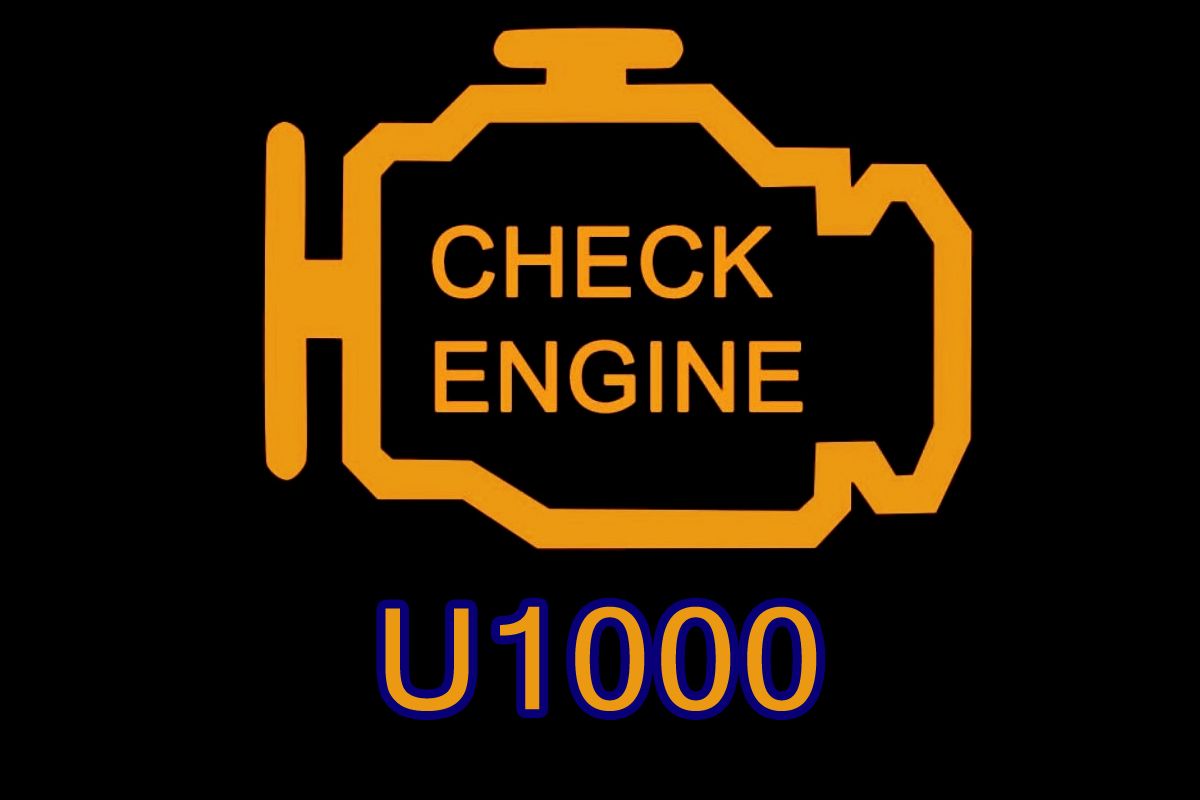
U1000 CAN Communication Line Signal Fault
U1000 is one of those diagnostic codes that can easily lead to the wrong part being replaced.
Unlike a conventional engine fault code that points toward a sensor, solenoid, or actuator, U1000 concerns communication between electronic control modules. The vehicle contains multiple computers, and these modules need to exchange information continuously. The CAN network provides the electrical communication path that allows them to do this.
When a control module detects an abnormality in CAN communication, it can store U1000.
The important point is that U1000 does not automatically mean that the CAN wiring itself is defective. The underlying problem can be related to wiring, connectors, power supply, grounds, network termination, electrical interference, or even a module that has stopped communicating correctly.
Think of U1000 as a network problem
Modern vehicles may have separate modules for:
-
Engine management
-
Transmission control
-
ABS/ESC
-
Airbag/SRS
-
Body control
-
Instrument cluster
-
Electric power steering
-
HVAC
-
Immobilizer
-
Parking assistance
-
Infotainment
These modules constantly exchange information.
For example, the engine module may need vehicle-speed information from another module. The transmission module may need engine torque information. The ABS module may share wheel-speed information with other systems.
If communication becomes unreliable, a module can no longer trust the information it receives.
That is where U1000 becomes important.
What does “CAN communication line” actually mean?
CAN stands for Controller Area Network.
It is a differential communication system generally using two signal lines:
-
CAN High
-
CAN Low
Instead of one module sending a dedicated wire to every other module, several modules can communicate over a shared network.
The electrical behavior of the two lines is what allows the network to distinguish valid CAN messages from electrical noise and other signals.
A problem with one of these lines can therefore affect several systems simultaneously.
The most important clue is not the code itself
When diagnosing U1000, one of the first questions should be:
How many modules are reporting communication problems?
This can tell you much more than simply seeing U1000 in one module.
If only one module reports a communication fault while every other module communicates normally, the problem may be close to that particular module.
If several modules simultaneously report communication faults, the investigation should expand toward the network itself.
For example, multiple communication codes appearing immediately after a weak battery event can point toward a power-supply problem rather than several failed modules.
Likewise, a group of modules becoming unavailable at the same time can indicate a common CAN branch, connector, ground, fuse, or power supply problem.
U1000 after a weak battery is possible
CAN modules are sensitive to their electrical environment.
A severely discharged battery, voltage drop during starting, incorrect jump-start procedure, or unstable charging system can create communication errors.
Therefore, if U1000 appeared immediately after:
-
A dead battery
-
Battery replacement
-
Jump-starting
-
Alternator problems
-
Battery terminal removal
-
Electrical repair
the battery and charging system should not be ignored.
Check the vehicle's actual voltage according to the manufacturer's specifications rather than relying on a generic number as proof of system health.
A battery can show acceptable voltage at rest and still experience excessive voltage drop during cranking.
A module that has disappeared from the network is a major clue
A useful diagnostic question is:
Can the scan tool communicate with every module that should be present?
If one module cannot be accessed, do not immediately conclude that the module itself has failed.
The module may have:
-
Lost battery power
-
Lost ignition power
-
Lost ground
-
A blown fuse
-
A damaged connector
-
CAN High or CAN Low interruption
-
A shorted communication line
-
Internal electronic failure
The distinction is important because replacing a module that simply has no power will not solve the problem.
Start with a complete vehicle scan
With U1000, scanning only the engine ECU is often inadequate.
Perform a complete network scan if the diagnostic equipment supports it.
Record:
-
All current codes
-
Stored codes
-
Pending codes
-
Communication codes
-
Which modules are accessible
-
Which modules are missing
-
Freeze-frame information where available
-
The order in which the faults occurred
The combination of codes can be more valuable than U1000 itself.
For example, if the engine module, ABS module and transmission module all report communication faults at the same time, that pattern deserves more attention than treating each code as an independent failure.
Don't start by replacing the CAN network
The CAN network is not a single replaceable component.
The actual vehicle network may contain:
-
Main CAN wiring
-
Branches
-
Connectors
-
Junctions
-
Control modules
-
Network termination components
-
Power and ground circuits
A fault in one area can affect a large section of the network.
This is why a wiring diagram is extremely valuable.
You need to know which CAN network the affected module belongs to and which other modules share that network.
Inspect the physical network
Before performing complicated electrical tests, inspect accessible wiring and connectors.
Look for:
-
Water intrusion
-
Corrosion
-
Loose terminals
-
Bent pins
-
Damaged insulation
-
Harness chafing
-
Previous aftermarket wiring
-
Accident-related harness damage
-
Poorly repaired wires
-
Connectors that are not fully locked
Water intrusion deserves special attention.
A connector that has become wet can cause intermittent CAN communication faults that appear and disappear depending on temperature, humidity, vibration, or vehicle movement.
CAN faults can be caused by a short circuit
A short involving CAN High or CAN Low can disrupt communication.
Depending on the fault, you may encounter:
-
CAN High shorted to ground
-
CAN Low shorted to ground
-
CAN High shorted to battery voltage
-
CAN Low shorted to battery voltage
-
CAN High shorted to CAN Low
-
Open CAN High
-
Open CAN Low
-
High resistance in the network
The exact electrical behavior depends on the vehicle's network architecture.
This is why blindly measuring a connector and comparing it with a generic internet voltage value is not a reliable diagnostic method.
Resistance testing can provide useful information
With the vehicle powered down according to the manufacturer's procedure, technicians may perform resistance checks on the CAN network.
Many conventional CAN networks use termination resistors at the ends of the network, so the measured resistance across the network can provide useful information about the network's electrical condition.
However, the expected measurement is vehicle-specific.
The presence of multiple networks, gateways, modules, and different architectures means that a generic resistance number should never be treated as universal proof.
If the manufacturer's procedure specifies a particular resistance test, follow that procedure.
Why continuity testing can be misleading
A CAN wire may have continuity from one point to another and still cause communication problems.
For example, a damaged conductor might make electrical contact when the harness is stationary but develop high resistance when:
-
The engine moves
-
The harness vibrates
-
The connector heats up
-
The vehicle passes over rough roads
-
Moisture enters the connection
A simple continuity beep will not necessarily reveal this.
For difficult intermittent U1000 faults, technicians may need to use:
-
Voltage-drop testing
-
Oscilloscope testing
-
CAN waveform analysis
-
Harness movement tests
-
Network monitoring
-
Module-by-module isolation
The oscilloscope can reveal what the scan tool cannot
A scan tool tells you that communication is failing.
An oscilloscope can help show what the electrical network is actually doing.
A healthy CAN waveform has characteristic differential behavior between CAN High and CAN Low.
Distorted signals, missing transitions, abnormal voltage levels, excessive noise, or other waveform abnormalities can provide important clues.
This becomes particularly valuable when U1000 is intermittent and the wiring looks visually perfect.
One faulty module can disturb the entire network
This is an important diagnostic possibility.
A control module that internally develops a short or abnormal electrical condition can interfere with the CAN network.
When this happens, other modules may also begin reporting communication faults.
The technician may therefore see a large number of U-codes even though only one module is actually responsible.
This is why the number of communication codes does not necessarily equal the number of failed modules.
In some cases, temporarily isolating suspected modules according to the manufacturer's diagnostic procedure can help identify which device is disturbing the network.
Modules should not simply be unplugged at random, especially on systems involving safety-critical components.
Power and ground should be checked before condemning a module
A module cannot communicate properly if its electrical supply is unstable.
Check the affected module's:
-
Battery power
-
Ignition power
-
Grounds
-
Relevant fuses
-
Relay outputs
-
Connector terminals
Ground problems are particularly deceptive.
A module can have enough electrical power to partially wake up but still fail to operate correctly because of a poor ground connection.
This can produce communication problems that look like a CAN fault.
Gateway problems deserve attention
Some vehicles use gateway modules to connect different CAN networks.
For example, the vehicle may have separate communication networks for different systems, with a gateway controlling the exchange of information between them.
If the gateway loses power or develops a communication problem, several apparently unrelated systems can become inaccessible.
Therefore, when multiple modules suddenly disappear from the diagnostic scan, determine whether they share a gateway or network path.
Aftermarket equipment can create U1000
U1000 can sometimes appear after installation or modification of electrical equipment.
Possible examples include:
-
Aftermarket multimedia systems
-
Remote starters
-
Alarm systems
-
Tracking devices
-
Performance modules
-
Diagnostic accessories
-
Incorrectly installed CAN interfaces
Improperly connected aftermarket equipment can load a CAN network or interfere with communication.
If the problem began immediately after an electrical modification, that history is diagnostically valuable.
U1000 does not necessarily mean the vehicle will stop
The seriousness depends on which communication network is affected and which module is unable to communicate.
If the affected communication is between non-critical convenience systems, the vehicle may continue to operate with relatively minor symptoms.
If communication involving the engine, transmission, ABS/ESC, steering, or other critical systems is affected, the consequences can be much more significant.
Possible symptoms include:
-
Multiple warning lights
-
Check Engine Light
-
ABS/ESC warning
-
Transmission warning
-
Instrument cluster abnormalities
-
Loss of certain driver-assistance functions
-
Starting problems
-
Limp mode
-
Transmission shifting problems
-
Intermittent electrical behavior
-
Multiple modules becoming inaccessible
A vehicle displaying several warning lights at once should not automatically be assumed to have several unrelated failures.
They may all originate from one communication problem.
An effective U1000 diagnostic path
A logical diagnosis can be built around the network rather than around individual parts.
Begin with the complete scan.
Determine which modules communicate and which do not.
Then identify the common denominator.
Do the affected modules share a CAN network, gateway, fuse, power supply, ground, or connector?
Next, verify vehicle voltage.
Check battery condition, cranking voltage and charging-system performance.
Then inspect the network physically.
Pay particular attention to connectors, water intrusion, harness damage and previous repairs.
After that, test the CAN electrical system.
Follow the manufacturer's procedures for resistance, voltage, voltage drop and network integrity.
If necessary, examine the CAN waveform.
An oscilloscope can help identify signal abnormalities that conventional testing misses.
Finally, investigate individual modules.
If the network itself is healthy but one module consistently fails to communicate, its power, ground, wiring and internal operation should be investigated.
What should not be replaced just because U1000 appears?
Several expensive mistakes are possible.
Do not automatically replace:
-
The ECM
-
The BCM
-
The TCM
-
The ABS module
-
The CAN wiring
-
The gateway
simply because U1000 is stored.
A communication code tells you that communication is abnormal. It does not identify the failed component by itself.
Module replacement can also introduce additional requirements such as programming, coding, configuration, immobilizer synchronization, or calibration.
A useful way to interpret U1000
Think of U1000 as a warning that says:
“The electronic modules are not communicating as expected.”
The next question is not:
“Which module should I replace?”
It is:
“Where in the communication chain is the failure occurring?”
That change in thinking makes U1000 much easier to diagnose.
The problem may be at the network wiring, a connector, a power or ground circuit, a gateway, or a single module disturbing the network.
The diagnostic takeaway
U1000 is fundamentally a vehicle network communication fault. It should be diagnosed at the system level rather than treated like an ordinary sensor or actuator code.
The most valuable information usually comes from the complete list of modules and codes, especially which modules can communicate and which ones cannot.
From there, the diagnosis should move through power and grounds, network wiring, connectors, termination, CAN signal quality and individual module behavior.
The key lesson is simple: U1000 identifies a communication problem, not a specific failed part. Replacing an ECU or other expensive module without proving that it is the source of the network failure is one of the easiest ways to turn a relatively simple CAN fault into an expensive repair.